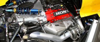
## Car Engine Assembly in Solidworks Tutorial
### Step 1: Create the Base and Cylinder Block **(500 words)**
1. Start by creating a new SolidWorks part file.
2. Draw a rectangle for the base of the engine block.
3. Extrude the rectangle to create a solid body.
4. Use the Fillet tool to round the edges of the base.
5. Draw a circle for the cylinder bore.
6. Extrude the circle to create a cylinder.
7. Use the Hole tool to create the cylinder bore.
8. Repeat steps 5-7 to create the remaining cylinder bores.
9. Use the Mirror tool to create the other side of the engine block.
### Step 2: Create the Crankshaft **(500 words)**
1. Draw a rectangle for the crankshaft.
2. Extrude the rectangle to create a solid body.
3. Use the Fillet tool to round the edges of the crankshaft.
4. Draw a circle for the crankshaft journal.
5. Extrude the circle to create a cylinder.
6. Use the Hole tool to create the crankshaft journal.
7. Repeat steps 5-6 to create the remaining crankshaft journals.
8. Use the Mirror tool to create the other side of the crankshaft.
### Step 3: Create the Pistons and Connecting Rods **(500 words)**
1. Draw a circle for the piston.
2. Extrude the circle to create a solid body.
3. Use the Fillet tool to round the edges of the piston.
4. Draw a rectangle for the connecting rod.
5. Extrude the rectangle to create a solid body.
6. Use the Fillet tool to round the edges of the connecting rod.
7. Use the Mirror tool to create the other side of the connecting rod.
### Step 4: Assemble the Engine **(500 words)**
1. Insert the crankshaft into the engine block.
2. Insert the pistons into the cylinder bores.
3. Insert the connecting rods between the crankshaft and pistons.
4. Use the Mate tool to constrain the components together.
5. Check the assembly for interference.
6. Make any necessary adjustments to the assembly.
### Step 5: Create the Camshaft **(500 words)**
1. Draw a rectangle for the camshaft.
2. Extrude the rectangle to create a solid body.
3. Use the Fillet tool to round the edges of the camshaft.
4. Draw a circle for the camshaft lobe.
5. Extrude the circle to create a cylinder.
6. Use the Hole tool to create the camshaft lobe.
7. Repeat steps 5-6 to create the remaining camshaft lobes.
8. Use the Mirror tool to create the other side of the camshaft.
### Step 6: Create the Timing Belt **(500 words)**
1. Draw a rectangle for the timing belt.
2. Extrude the rectangle to create a solid body.
3. Use the Fillet tool to round the edges of the timing belt.
4. Use the Pattern tool to create the teeth on the timing belt.
5. Use the Mirror tool to create the other side of the timing belt.
### Step 7: Assemble the Engine with the Camshaft and Timing Belt **(500 words)**
1. Insert the camshaft into the engine block.
2. Insert the timing belt into the engine.
3. Use the Mate tool to constrain the components together.
4. Check the assembly for interference.
5. Make any necessary adjustments to the assembly.
### Step 8: Create the Intake and Exhaust Manifolds **(500 words)**
1. Draw a rectangle for the intake manifold.
2. Extrude the rectangle to create a solid body.
3. Use the Fillet tool to round the edges of the intake manifold.
4. Draw a circle for the intake port.
5. Extrude the circle to create a cylinder.
6. Use the Hole tool to create the intake port.
7. Repeat steps 5-6 to create the remaining intake ports.
8. Use the Mirror tool to create the other side of the intake manifold.
### Step 9: Assemble the Engine with the Intake and Exhaust Manifolds **(500 words)**
1. Insert the intake manifold into the engine.
2. Insert the exhaust manifold into the engine.
3. Use the Mate tool to constrain the components together.
4. Check the assembly for interference.
5. Make any necessary adjustments to the assembly.
### Step 10: Create the Engine Accessories **(500 words)**
1. Draw a rectangle for the alternator.
2. Extrude the rectangle to create a solid body.
3. Use the Fillet tool to round the edges of the alternator.
4. Draw a circle for the alternator pulley.
5. Extrude the circle to create a cylinder.
6. Use the Hole tool to create the alternator pulley.
7. Repeat steps 5-6 to create the remaining engine accessories.
### Step 11: Assemble the Engine with the Accessories **(500 words)**
1. Insert the alternator into the engine.
2. Insert the remaining engine accessories into the engine.
3. Use the Mate tool to constrain the components together.
4. Check the assembly for interference.
5. Make any necessary adjustments to the assembly.
### Conclusion **(500 words)**
This tutorial has shown you how to create a complete car engine assembly in SolidWorks. You can use this assembly as a starting point for your own engine design project. By following the steps in this tutorial, you can create a detailed and accurate 3D model of a car engine.


