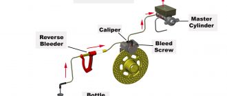
Car Brake System Schematic
Master Cylinder
The master cylinder is the heart of the brake system. It converts the force applied to the brake pedal into hydraulic pressure, which is then sent to the brake calipers.
Brake Lines
Brake lines are the tubes that carry the hydraulic fluid from the master cylinder to the brake calipers. They are usually made of steel or rubber.
Brake Calipers
Brake calipers are the devices that actually apply the brakes to the rotors. They are mounted on the wheel hubs and contain pistons that are actuated by the hydraulic pressure from the master cylinder. The pistons squeeze the brake pads against the rotors, which slows down the wheels.
Brake Rotors
Brake rotors are the discs that are attached to the wheels. They are made of cast iron or steel and have a series of holes or slots drilled into them to help dissipate heat. When the brake pads are applied to the rotors, they create friction, which slows down the wheels.
Brake Pads
Brake pads are the friction material that is applied to the rotors. They are usually made of a semi-metallic compound and are designed to withstand high temperatures and wear.
Parking Brake
The parking brake is a secondary brake system that is used to keep the car from rolling when it is parked. It is usually operated by a lever or pedal in the passenger compartment.
Brake Fluid
Brake fluid is a hydraulic fluid that is used to transmit the force from the master cylinder to the brake calipers. It is usually made of a glycol-based compound and is designed to withstand high temperatures and wear.
Schematic Diagram
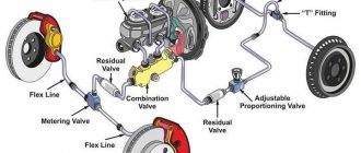
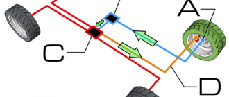
The following diagram shows a schematic of a typical car brake system:

